This happened more than a decade ago. At that time we had very few information on LEDs, which were becoming ubiquitous in lighting applications at a fast pace.
By then, besides what the locals call R&D, I was also in charge of the tech support team.
This customer approached us with a strong claim: the LEDs he bought were defective. He claimed to be powering them “at the exact threshold voltage”, but some LEDs will quickly become brighter and brighter, then dimming to the point of being unusable.
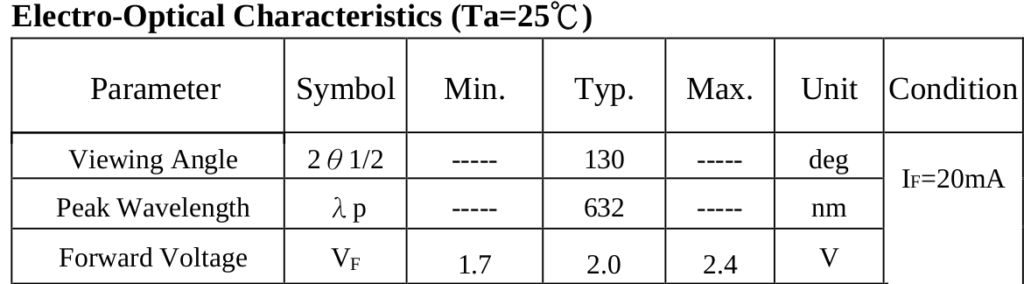
The first question that came to our minds was “what would be the ‘exact’ operating voltage for an LED ?”, but we thought he was assuming ‘typical’ meant “for all practical purposes: always”. A quick look at the datasheet revealed a strong spread in the expected voltage at a known current, as we can see in this typical datasheet extract:
He had bought quite a bunch of cheap LEDs with no bin separation and he somehow believed all of them would have the same working point.
Nevertheless, we asked for the schematic, which conceptually was sort of something like the figure:
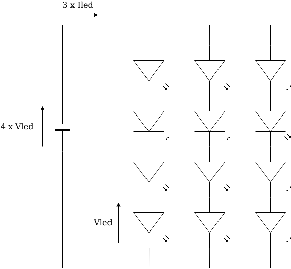
We then advised him to search for literature regarding how to connect diodes in parallel, or if he couldn’t find that, concepts in paralleling power transistors would shine some light.
What he was experiencing was the following: when you power such a parallel circuit, voltage will be the same for all branches, but unless you carefully match all LEDs (and perhaps even so), LEDs will have slightly different operation curves, that’s what those ‘min’, ‘max’, and ‘typ’ mean. “Vled” in the schematic above will be different for every LED and can be anywhere between ‘min’ and ‘max’, with some probability of falling around ‘typ’. That is, driven with a (let’s say) 20mA source, many LEDs will exhibit a voltage drop of ‘typ’, while a number of others will measure values closer to ‘min’ or ‘max’. Conversely, the situation becomes exponential instead of logarithmic and here is where things get interesting, as we are to expect a much wider variation in LED current with small variations in the applied voltage.

The branch with more LEDs whose working voltage (at the branch current) is on the “closer to ‘min'” side of the distribution curve, will add up to “a lower voltage”, but since it is connected in parallel to the other branches, it must share the same voltage. As a result, this branch will draw more current to move the operating point to the voltage imposed by the parallel circuit.
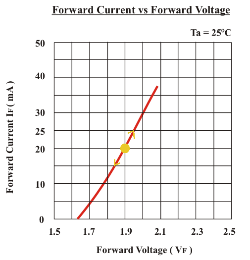
And here comes the tail-chasing game. Those LEDs in that branch that had a higher voltage (at the branch current) will heat up more, since their VxI is higher. As we know, these semiconductor junctions have a negative temperature coefficient, that is, junction voltage is inversely proportional to its temperature, so when temperature increases, voltage across the junction will decrease when current is taken constant. (Let’s pay attention to the presence of ‘T’, the absolute temperature, in the Shockley model equation above, and also the note “Ta=25ºC” in the datasheet extract and curve above)
So, as voltage decreases, the branch will take more current to cause the voltage to rise, causing the LED to heat up some more, and so on until, in the absence of anything limiting the current, something undesired happens: the LED will let the fumes out, and once that vital fluid escapes, it will no longer work… 😉
As LED brightness is proportional to current, and color depends on temperature, the LED brightness increases while color changes, up to a point where the junction no longer works as expected and so brightness is minimum; probably protecting the other LEDs but that really depends on the different failure modes.
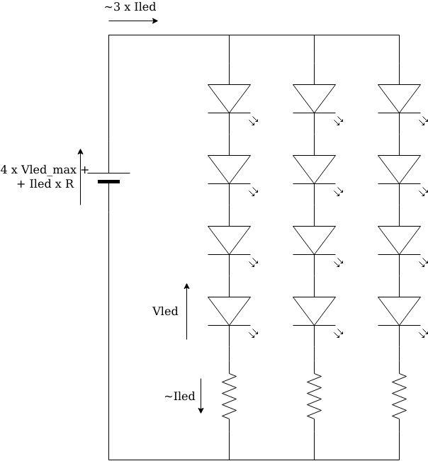
We also told him he needed to, at least, add some negative feedback to the circuit: a series resistor inside each and every branch; as done when paralleling diodes or power transistors.
The operation is as follows:
When one of the branches starts taking more current, the resistor turns that into a voltage that is subtracted from the branch supply voltage, causing the LEDs in that branch to see a lower voltage and so take less current. A small value, enough to compensate the threshold voltage spread, would do. The “exact” value of that resistor will depend on the LEDs and the number of them in series, and of course we can’t expect to still be able to power the circuit at the sum of the typical voltages as this customer intended to do, and the solution would be as effective as one manages to juggle all the variables and still choose a viable value for the resistors; but though we’ll keep the LEDs alive, we’ll still have some brightness differences among the branches.
A more complex but stable thing to do, is to dedicate a current source for each branch. As we know, LED brightness depends on its current, so we control the brightness by keeping the branch current constant, and each branch has its current source, all powered from the voltage source (since we don’t have ideal current sources but transistor-based circuits that keep current relatively constant within certain limits).
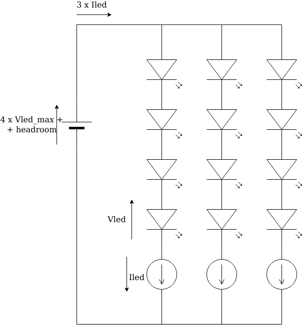
Current will still vary with temperature, so if we really need to keep brightness tightly constant, we’ll need to stabilize our current sources for changes in temperature.
More expensive LEDs, where the manufacturer has separated them in bins or groups with similar characteristics, also present some spread:
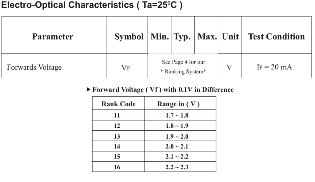
As we can easily calculate, even that 0.1V difference can cause a great difference in current when connected in parallel, but with carefully selected LEDs those differences can be minimized and more simple circuits can be built. We somehow shift circuit complexity to provisioning logistics.
On a higher detail, LEDs, as diodes, deviate from this ideal exponential response, which can be modeled via a small series equivalent resistance. This resistance can provide a certain degree of regulation, but since in general there is no available data, this would require lots of development effort and is not guaranteed to be successful.
