Everything started with a phone call, one of my clients had just got a complaint from one of his retail buyers, this device had been freezing and remaining unresponsive, having to be power cycled to recover. Since these appliances were directly attached to the mains power when installed, this required operating on the switch breaker for that part of the house, also affecting other appliances in that area.
At that time we already had several thousand of these controller boards in the field; since this one was the only one with such a failure, and this customer was located at a country place, life went on and I thought my customer had somehow solved it. A watchdog failure was something very unlikely, so it should have been something related to the power supply or some thermal issue, those places are either too cold or too hot….
Months later, a rather similar failure shows up again on another location, also relatively far away from a city, but this time the end user was a strategic customer living on a private neighborhood; as it always happens, hard to solve failures happen in places where damages can be most harmful, Murphy…
The company selling this appliance had sent several technicians, who had changed controller boards at will, but the problem still persisted, so we decided to pay a visit to this customer and run some measurements there. Surprisingly enough, we could not only confirm that this customer was right, but we also observed huge fluctuations on the mains voltage, sometimes getting over 250V (we have 220V mains here). The oscilloscope confirmed that the controller board built-in power supply stopped working, starting again after a power cycle; something looking like a safety protection or a self power-off feature…
After confirming there were no temperature issues involved (this chip also included some thermal protection features), I went back to my lab carrying this board with me, with the intention to reproduce this issue there and meditate on what could be causing it. The first one in a series of profound revelations I found by playing with the variable autotransformer (variac) knob. Even though the power supply was working correctly at such a high voltage, sometimes I could reproduce this issue by simulating sharp changes in mains voltage. Then, the use of a mains voltage stabilizer that has been modified for manual switching, allowed me to almost reproduce this issue at will.
The second revelation I found in the datasheet: one of the controller pins had this functionality associated to an internal finite state machine whose description was a very good match to what we’ve been observing, but that pin was correctly decoupled by a capacitor connected to ground, as the datasheet stated.
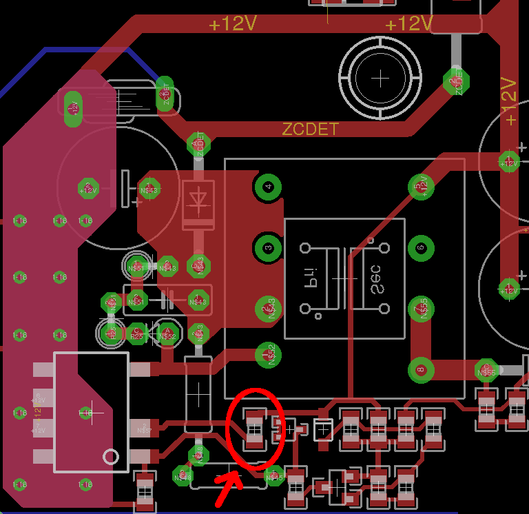
After reading the pin descriptions for each and every controller pin dozens of times, I came to a conclusion: “something”, “somehow”, was causing voltage in that pin to raise. Something strange was happening around that capacitor in the figure…
The third revelation happened once I could observe the voltage at that pin with great detail: it barely raised at times when “mains voltage” sharply changed when above 240V. Then, the power supply stopped working until it was power cycled. We had found what was going on, now we only had to find what was causing it…
Satori came when observing the PCB design, while analyzing (once again) current loops, but this time deeply focusing on the path to ground for this decoupling capacitor.
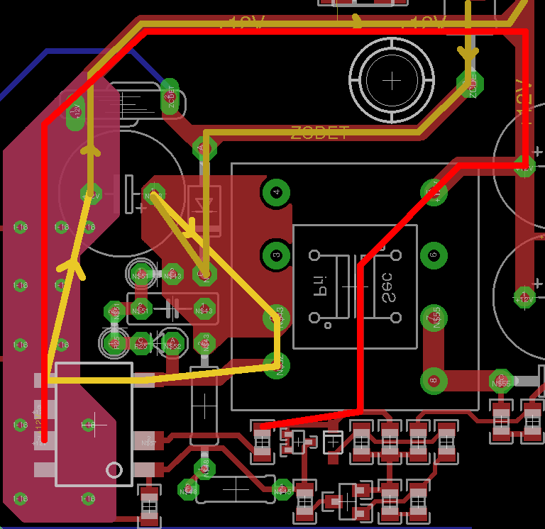
The light mustard trace depicts the power supply switching current, intentionally having a reduced area to avoid generating excessive noise that could interfere with the rest of the circuit. The dark mustard trace shows the input current coming from the mains power… shared with circuitry serving other features for the appliance operation, but also, and mainly, shared to a great extent with the light red trace, which belongs to this very decoupling capacitor’s ground return path.
Though we can trust that thick trace on both layers doubling also as a heatsink, let’s pay attention to that “unrolled inductor” running horizontally in the screen. We can see that both the switching power supply current pulses, that are stronger when higher currents come into play, and the filter capacitor charging pulses, that are stronger when there are mains instabilities, circulate on a long path that is shared with the decoupling capacitor connecting path to ground. We can think of this as if that capacitor is connected to ground via an RL series circuit (the PCB track impedance), and in that node we also connect other circuitry to carry their currents to ground… Technically speaking, we have a sensitive circuit requiring a low impedance path to ground and we are using an inadequate impedance path that also, and for worse, carries strong currents with a high di/dt, and we all know what happens when high di/dt circulates through -L, isn’t it?.
To solve it, we replaced that capacitor for a through-hole component, connecting its ground return path straight through using a different, star-shaped path, to the chip reference ground; away from the switching circuit and the input current, as good practices and datasheet state…
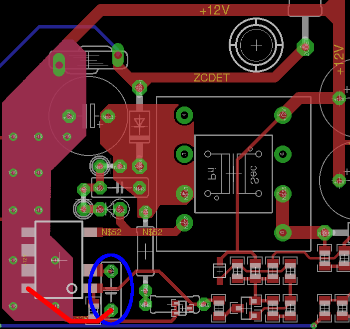
The figure shows this new path. Though we also share this SOT-323 double diode path to ground, its current is low enough to be dismissed.