(meditations on academically correct content in technical articles and application notes)
Some days ago, I was chatting with an old friend and mentor about electronic design stuff, and he raised the latch-up subject. Later, while I was reviewing an article inside my head (one I haven’t written yet), I recalled a similar example, on a different realm, that brought this to my mind, and so it takes form in this post.
My thoughts were pondering how bad some features and ease of use can be, when we consider teaching and educational aspects. Around 2004, I attended a developer’s conference from a famous company selling “easy” microcontrollers (that are in reality the hardest thing to approach for someone who already knows what a microcontroller is and happens to work on many of them from different brand names). The presenter was showing an application note on which I could see a relay connected to a microcontroller I/O port (GPIO), to which I respectfully questioned if, at least, wasn’t it a bit convenient to add a flywheel (or “protection”) diode in there, and he confidently answered “all our microcontrollers have protection diodes in GPIO pins”.
Let’s start by saying that I’m one of those engineers who don’t use built-in weak pull-ups unless there is a reason to use them. Why? Because I try to keep my design as independent from manufacturer details as possible (in the future I might port this design to a “difficult” microcontroller, not having these cute add-ons), and also firmware independent; saving those tenths of a cent (setting PCB real estate aside) does not justify me being attentive to remembering to enable pull-ups or later find unintended operation up to the point when the code hits that instruction. In addition, in ultra-low power designs those internal weak pull-ups are unpredictable and can even be counterproductive. Furthermore, to anyone not having the design log (if it exists), there is no clue on the “academic” reason why that resistor has to be there, and all it says about the rest of the circuit; to me that is very important in an application note, as it is an engineering document.
Back to this relay being controlled by a GPIO, let’s say this leads to an enthusiast probably learning conflictive techniques that he may later replicate in other realms when he advances (I feel tempted to remind you all of the effects of using only BASIC to teach youngsters how to program in the 80’s).
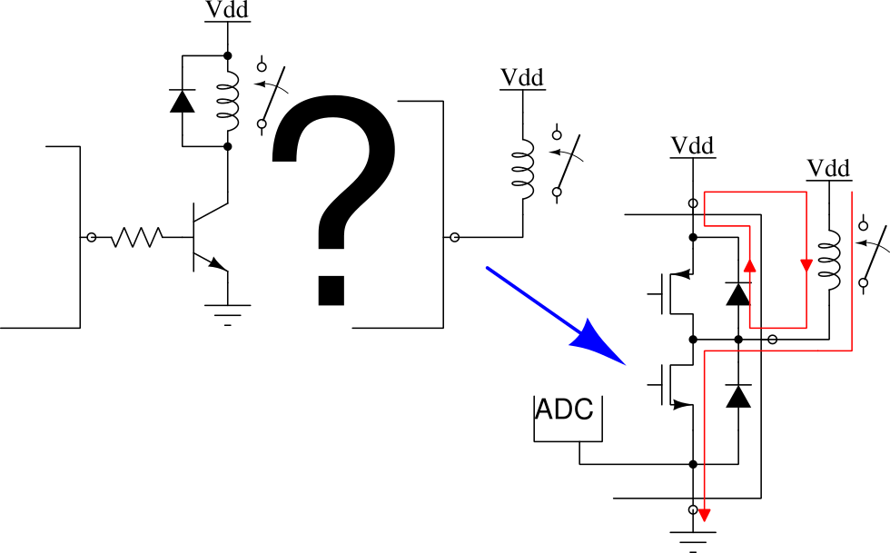
First issue: the current through the relay. GPIOs usually present a MOS push-pull structure, that is, a P-channel MOSFET sources current from the power supply while a N-channel MOSFET drains current to ground. These MOSFETs usually have different areas, being the N-channel one bigger and so having more current capacity, and in many cases even not enough to drive a relay. Depending on how this relay is connected, it may operate correctly because the GPIO does not raise the output voltage too much, as the N-channel MOSFET is able to handle that current; or it may operate erratically because the GPIO lowers the output voltage too much, as the P-channel MOSFET is not able to handle that current. Other side of this is that, depending on how this relay is connected, its current will flow through the GND pin or the VDD pin, that is, it will enter the microcontroller through the power pin, coming from the power supply, or will return to it through the ground pin, creating, among other things, current circulation in unintended paths, and this can affect operation during relay turn-on and turn-off transients. This can be caused by parasitic inductance in the PCB tracks, and by loop antennas formed by the current flowing on one path and returning on a different path, that irradiate in all directions with an intensity that is proportional to the loop area. The current flowing on the ground pin can also affect measurements on a built-in analog-to-digital converter (the current on the power pin can also do it if the microcontroller saves the analog section power pin, VDDA).
Second issue: the current that should stop flowing through the relay when it opens, but due to it being an inductor, Faraday and Lenz conspire against us: V = -L di/dt.
When we want to open the relay, we need to set the GPIO on a high-impedance state, or at least the opposite state to which we used to turn it on. Let’s suppose we activate it by connecting it to ground, so ideally we should now configure an open-drain pin or at least connect it to the positive power supply. Being the relay coil an inductor, its current can’t stop flowing immediately, it will try to keep flowing. Depending on how hard it is for the inductor “to keep this current constant” (di/dt), it will develop a voltage on its terminals, and this will have the polarity it needs to cause that current to flow, and a value proportional to the inductance. That polarity causes the voltage at the microcontroller pin to be higher than its power supply voltage, as much as it needs in order to cause that current to flow. On which path will this current flow ? Ideally through a flywheel diode, connected in parallel with the relay coil, using the appropriate polarity. Being it absent, through wherever the induced high-voltage may find the path; in this very case, through the protection diode in the GPIO, returning to the relay by the power trace that connects them (in the opposite direction, producing a voltage raise in the microcontroller power supply), if we set the pin in a high-impedance state. If, on the other hand, we set the pin as a positive output, it will have to flow through the P-channel MOSFET, also in the opposite direction, probably through the intrinsic diode that can be found in the crystalline structure, and usually behaves as protection diode; or trough a real protection diode, whatever presents the lower impedance, and following the same path we already mentioned.
Let’s assume those protection diodes are designed to withstand the current flowing through the relay coil, and the rest of the circuit can cope with these effects without issues. What happens if we replicate this design using a microcontroller with no built-in protection diodes ? (These diodes are often undesirable, but this article will become too long…)
Some paragraphs above we said “through wherever the induced high-voltage may find the way”. Sometimes that path can be through some internal peripheral, producing erratic behavior; others, something much more risky can happen.
In semiconductor chip structures, some parasitic PNPN structures can be formed; this is an undesired thyristor. This thyristor may trigger via a trigger current if something is able to inject enough current through the block operating as the gate (depending on polarity); or via overvoltage, if enough voltage develops at the ends of this structure, exceeding its breakdown voltage. This parasitic thyristor then turns on and will stay on until the power supply is removed; most likely the crystalline structure will melt as it isn’t able to dissipate the excess of heat, forming a short circuit. Latch-up.
Therefore, it is often much more educational to control the relay using a transistor and place the necessary flywheel diode, carrying the relay current away from the A/D converter. Otherwise, we can place a comment warning us on the side effects we might have and the components we’ve been able to remove from the circuit thanks to this fancy feature; this might arise enough curiosity on the reader and push him to investigate further.
Even though new fabrication technologies minimize latch-up possibility, it is always convenient to place series resistors on those pins that might be exposed to voltages higher than the power supply voltage, in order to limit a possible trigger current and also help to extinguish current through the thyristor, or at least limit it so it does not destroy the crystalline structure.