GPIO handling in ARM Cortex-M

Let’s start by analyzing what flipping an I/O port really means.

The minimum number of instructions when using bit banding is three:

  • one processor register must be a pointer to the I/O register
  • another register will contain the value to be written
  • an indexed write instruction performs the operation

The following actions we may perform on that same port, can be carried using only two instructions, or even one if we are able to reuse a register containing the value to be written (0 or 1).

Operations modifying several bits at once require that we read the I/O port copying its contents to a processor register, modify that register, and then write that register back to the I/O port (except in cases where the microcontroller has purposely built hardware, like some STM32’s, but let’s focus on the Cortex-M itself).

Any operation we’d like to perform over a peripheral, will essentially abide to wait we just stated. This process, in fact, takes a very small amount of time for the processor core. Due to the internal bus structure, the timing for successive actions over an I/O port is determined by the corresponding transactions over first the AHB bus and then the APB bus, added to the time it takes for the processor to request those changes (instruction execution). Even though every microcontroller has its own peripherals, chosen by the manufacturer, we usually encounter access times in the order of several hundreds of nanoseconds, due to the fact that the minimum switching time (either low to high or high to low) in an I/O pin is determined by the maximum transfer speed in those buses, which corresponds to two clock cycles for each of them.

The processor may perform other activities during that time, but it can’t operate on that very same port; in that case the execution of the second instruction is delayed until the first one can be completely performed and the bus is freed to accept another request.

For example, in a microcontroller family like the HT32F125x from Holtek, Cortex-M3, the AHB bus clock and the APB bus clock are user configurable up to a maximum of 72MHz, which is also the default value. To this we have to add the processor instruction execution time. Thus, we can estimate the minimum possible latency time as four clock cycles (∼ 50ns), that is, once the instruction to move a pin has executed, it must go through the AHB bus to the APB bus to reach the peripheral, the I/O port itself.

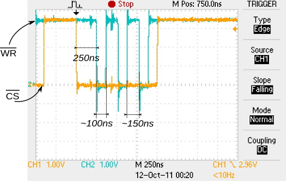
As we’ve seen, it is possible for the processor to perform other duties but it can’t operate on that same port again, so the second order gets delayed until the first one can finish, what gives a period of eight cycles (∼ 100ns), as we can see on the figure, a capture taken during the development phase of a color display driver:
Another possibility is that the AHB bus internal structure allows pipelining succesive requests, this can help to reduce some cycles from the total time.

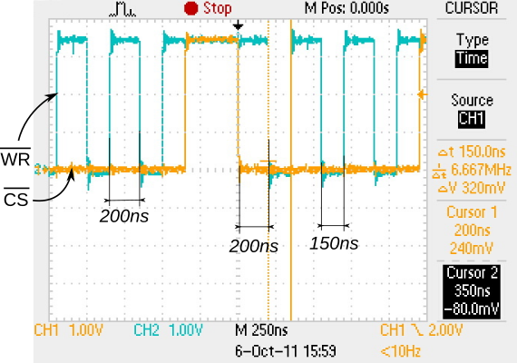
For example, for the TMPM330 from Toshiba, another Cortex-M3, the AHB bus clock and the APB bus clock are user configurable up to a maximum of 40MHz, and also the default value. This processor seems to have some form of pipelining in its AHB bus implementation, ’cause in the very same application we’ve observed a minimum period of six clock cycles (150ns), as can be seen in the following figure:
Up to here, everything is also valid for Cortex-M4 and Cortex-M0 processors.

The Cortex-M0+ processor can optionally have a Single-cycle I/O peripheral connected to its Bus Matrix, which, as its name suggests, allows performing input and output operations in just one cycle. That peripheral is memory mapped and can be accessed using regular data transfer instructions, but these are executed in one cycle instead of two cycles.

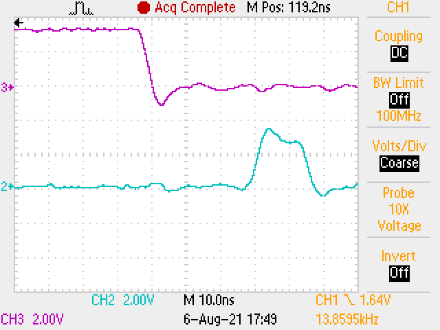
The next figure shows flipping a couple of GPIO pins on an STM32G071 running at 64MHz. The lower trace shows succesive set and reset operations in around 15ns:
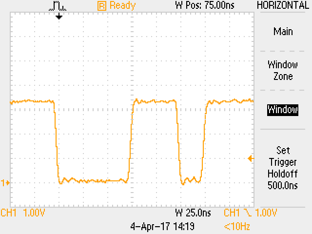
Regarding the I/O management process, and given that to operate on a pin we need to copy the required content from a register to memory, the actual operation in a single cycle would be limited to those cases in which it is possible to keep each required value in its own register and then use only memory transfer instructions in a row. The next capture shows the results of executing two successive read-modify-write operations, followed by two write operations, inside a loop (so we can easily see it), on a Holtek HT32F52231, a 40MHz Cortex-M0+. The first signal reset, at trigger time, includes the time needed to setup all necessary registers; so the time the signal stays in the high state is considerably longer. The first set can then be executed in three cycles (read, modify, write). The second reset takes two cycles (register load, write), while the next set can be executed in one cycle due to the optimizer being able to reuse one of the previously loaded registers:
This post contains excerpts from the book “Desarrollo con microcontroladores ARM Cortex-M3“, taken and translated with the author’s premission.

Manejo de GPIOs en ARM Cortex-M

Analicemos en detalle la operatoria para mover un pin de I/O.

La cantidad mínima de instrucciones mediante bit banding es de tres:

  • un registro del micro debe apuntar al registro de I/O
  • otro contendrá el valor a escribir
  • una instrucción de escritura indexada efectúa la operación propiamente dicha

Las operaciones siguientes que realicemos sobre el mismo port pueden hacerse con dos instrucciones, o incluso una si reutilizamos el registro que contiene el valor (0 ó 1).

Las operaciones de modificación de varios bits simultáneamente requieren de una lectura del port de I/O a un registro, modificación del registro, y escritura al port de I/O (excepto que el microcontrolador específicamente disponga de un hardware ad hoc como por ejemplo algunos STM32, pero hablemos del procesador Cortex-M en sí).

Cualquier operación que deseemos realizar sobre cualquier periférico, responderá en esencia a una de estas dos consideraciones vistas. Este proceso analizado demora muy poco tiempo en lo que respecta al procesador. Debido a la estructura interna de buses, el timing para acciones sucesivas sobre I/O viene dado por las transacciones en el bus AHB y luego el APB, sumado al tiempo del procesador para ordenar el cambio (ejecución de las instrucciones). Si bien cada micro tiene sus propios periféricos determinados por su fabricante, es común encontrarnos con tiempos de acceso de varios cientos de nanosegundos, debido a que el tiempo mínimo de conmutación en uno y otro sentido de un pin de I/O corresponde a la máxima velocidad de transferencia en estos buses, que es de dos ciclos de clock en cada uno.

Es posible que el procesador realice otras actividades en este tiempo, pero no que opere sobre el mismo port, en cuyo caso la ejecución de la segunda orden se demora hasta la finalización de la primera.

Por ejemplo, en un microcontrolador como el HT32F125x de Holtek, un Cortex-M3, el clock del bus AHB y el bus APB es configurable por el usuario, 72MHz como máximo y por defecto. A esto sumamos el tiempo de ejecución del procesador. Así, deducimos que el tiempo mínimo posible de latencia es de cuatro ciclos de clock (∼ 50ns), correspondiente al pasaje de la información de mover el pin desde la finalización de la instrucción hasta que pasa por el bus AHB y luego por el bus APB.

Como analizamos, es posible que el procesador realice otras actividades en este tiempo, pero no que opere sobre el mismo port, en cuyo caso la ejecución de la segunda orden se demora hasta la finalización de la primera, obteniendo un período de ocho ciclos de clock (∼ 100ns), como podemos apreciar en la figura, que corresponde al desarrollo de un driver para un display color:

Otra posibilidad es que la implementación interna del bus AHB permita realizar pipelining de sucesivas operaciones, con lo cual se reduce en algunos ciclos el tiempo total.

Por ejemplo para el TMPM330 de Toshiba, otro Cortex-M3, el clock del bus AHB y el bus APB es configurable por el usuario, 40MHz como máximo y por defecto. Al parecer este micro incorporaría pipelining en el bus AHB, pues en la misma aplicación hemos obtenido un período mínimo de seis ciclos de clock (150ns), como podemos apreciar en la figura:

Lo visto hasta aquí es válido también para Cortex-M4 y para Cortex-M0.

El procesador Cortex-M0+ incorpora de manera opcional en su Bus Matrix la conexión a un periférico que permite acceder a operaciones de entrada y salida en un solo ciclo: Single-cycle I/O. Dicho periférico está mapeado en memoria y puede ser accedido por las instrucciones corrientes de transferencia de datos, sólo que éstas se ejecutan en sólo un ciclo, en vez de dos.

La imagen siguiente muestra el movimiento de un par de GPIOs en un STM32G071 operando a 64MHz. En el trazo inferior observamos que un set y reset sucesivos se producen en unos 15ns:

En lo que al proceso de manejo de I/O se refiere, y dado que para operar sobre un pin es necesario copiar el contenido de un registro a memoria, la operación real en sólo un ciclo se limitaría a los casos en que es posible mantener los valores en sendos registros y utilizar sólo instrucciones de transferencia a memoria una tras otra. La imagen siguiente muestra el resultado de ejecutar dos operaciones de lectura-modificación-escritura sucesivas, seguidas por dos de escritura, dentro de un loop (para poder observarlo fácilmente), en un Holtek HT32F52231, Cortex-M0+ de 40MHz. El primer reset de la señal, al momento del disparo, incluye el seteo de los registros necesarios; por eso el tiempo en estado alto es considerablemente más largo. El primer set ya puede ejecutarse en tres ciclos (lectura, modificación, escritura). El segundo reset se ejecuta a los dos ciclos (carga de registro y escritura), mientras que el set siguiente se ejecuta en un ciclo dado que el optimizador del compilador ha podido reutilizar un registro cargado con anterioridad:

Este post contiene algunos extractos del libro “Desarrollo con microcontroladores ARM Cortex-M3“, con permiso del autor.