Timer expired, I think…

Quite often we have several ways to perform a task. Sometimes we choose based on personal taste or affinity, others there is a context that enforces certain rules that limit our safe choices.

When working with software timers, I usually choose to use an old scheme based on multiple independent timers that has found its way through the assembly languages of many different micros and has finally landed in C. Sometimes, due to 32-bits being available, I may choose to simply check the value of a counter. In both cases, each timer and the counter are decremented and incremented (respectively) in an interrupt handler.

This requires that (in C) we declare this variable volatile so the compiler knows that this variable might change at any time without the compiler taking action in the surrounding code. Otherwise, loops waiting on this variable will be optimized out.

extern volatile uint32_t tickcounter;

On the other hand, and due to the same reason, the access to this variable must be atomic, that is, it has to occur in a single processor instruction (or a non-interruptible sequence of them). Otherwise, the processor might accept an interrupt request in the middle of the instruction sequence that is reading the individual bytes forming this variable, and if this interrupt modifies this variable we would end up with an incorrect value. This happens, for example, if we use 32-bit counters/timers on most 8-bit micros; more info on this subject in another post.

Once we solve this issues, then there is the problem of counter length, the number of bits defining integer word size for our timers.

My timer scheme above is quite simple: each timer is decremented if it has a non-zero value, so to use one of this I simply write a value and then poll until I get a zero. There is obviously a jitter as there is a time gap from the moment I write the timer till it’s decremented by the interrupt handler, and another one since the timer reaches zero and the application reads the value.

However, reading a counter, on the other hand, poses some issues; and their solutions were the inspiration to write this post. Because of atomicity, we might end up being forced to use a small variable, a short length counter that will overflow in a short time.

What happens when this counter overflows ? Well, maybe nothing happens, if we take precautionary measures.

Everything will work as a charm and all tests will pass as long as the counter doesn’t overflow between readings, that is, counter length is enough for the application lifetime. For example, a 32-bit seconds counter takes 136 years to overflow. However a 16-bit milliseconds counter overflows every minute and fraction (65536 milliseconds).

If the time between counter readings is larger, there is the possibility that the counter may overflow more than once between checks. In this situation, we must use an auxiliary resource, as the counter alone can’t do it.

If, however, we can be sure that the counter will overflow at most once between checks, we just need to write proper code in order for our comparison to survive this overflow. Otherwise, as we’ve already said, everything will work fine most of the time, but “sometimes” (every time there is a counter overflow) we’ll get a glitch.

For the sake of this analysis, let’s consider the following scheme, we are using uppercase names in violation of some coding styles but we do it for counter highlight’s sake:

extern volatile uint32_t MS_TIMER;
uint32_t interval = 5000; // milliseconds
uint32_t last_time;

The following code snippets work fine, as the difference survives counter overflow and can be correctly compared to our desired value:

	last_time = MS_TIMER;

	if(MS_TIMER - last_time > interval)
	    printf("Timer expired\n");

	if(MS_TIMER - interval > last_time)
	    printf("Timer expired\n");

On the other hand, this does not work properly

uint32_t deadline;

	/* I must not do this
	deadline = MS_TIMER + interval;
	if(MS_TIMER > deadline)
	    printf("Timer expired\n");
	*/

If, let’s say, MS_TIMER is 0xF8000000 and interval is 0x10000000, then deadline will be 0x08000000 and MS_TIMER is clearly larger than deadline from the beginning, this causes the timer to expire immediately (and that is not what we want…).

A workaround is to use signed integers, and this works with time intervals up to MAXINT32 units:

int32_t deadline;
int32_t interval = 5000; // milliseconds

	deadline = MS_TIMER + interval;
	if((int32_t)(MS_TIMER - deadline) > 0)
	    printf("Timer expired\n");

To dive into more creative ways might result in timers that never expire when the counter is higher than MAXINT32, as this is seen as a negative number and so smaller than any desired time (that is a positive number); but do work when our device is started or reset. These can be considered as errors when choosing counter length (including sign).

As we’ve seen, some problems show themselves when referring to a time that is MAXINT32 time units after the system starts. This is usually 2^31, and this, for a milliseconds counter, is around 25 days; and for a seconds counter about 68 years. There can be several errors lurking deeply inside some Linux (and other Un*x-like) systems that will surface once they need to make reference to a time after year 2038 (the seconds counter starts at the beginning of year 1970).

If, on the other hand, we use 16- or 8-bit schemas…

In these examples we used ‘greater than’ in comparisons; this guarantees that the time interval will be longer than requested. If, for example, we set it right now and ask for a one second interval, and one millisecond later the interrupt handler increments the counter, should we use a ‘greater than or equal’ comparison our timer will expire immediately (well, in 1ms…). Also, if we set it 1ms after the interrupt took place it will expire in 1,999s instead of 1s. In a scenario where increment and comparison are not asynchronous, we can avoid jitter and use a ‘greater than or equal’ comparison.

On atoms and clocks

Interrupts, as their name implies, may interrupt the program flow of a microprocessor at any point, any time, even though sometimes they seem to intentionally do it in the most harmful way possible. The very reason of their existence is to allow the processor to handle events when it is not convenient to be waiting for them to happen or regularly poll for their status, or to handle those types of events requiring a fast and low latency attention.

When carefully utilized, interrupts are a powerful ally, we can even build multiple-task schemes assigning an independent periodic interrupt to each task.

When haphazardly used, interrupts may bring more problems than solutions; in particular, we can’t share variables or subroutines without taking due precautionary measures regarding accessibility, atomicity, and reentrability.

An interrupt may occur at any point in time, and if it occurs in the middle of a multi-byte variable update it can (and in fact it does) wreak havoc on other tasks. These may hold “partially altered” values that in the real world are incorrect values, and probably dangerously incoherent for the software. A typical and frequently forgotten example are timing or date and time variables. The main program happily takes these variables byte by byte in order to show them on the display screen, without thinking that, if they are updated by an interrupt, these are not restricted to being handled before or after our action and not in the middle of it. If those values are only shown at the display screen there is no further inconvenience, correct values will be shown one second later, but if they are logged or reported, we’ll be in serious trouble explaining why there is a record with a date almost a year off, as in the following example:

Though this blogger is a bit lazy on the graphics side, you might probably guess from the Spanish text that ‘1’ is the RTC value being read before the “one second” interrupt is handled, ‘2’ is that interrupt itself, ‘3’ is the RTC value finally read after the interrupt took place. The left column holds the RTC value while the right column shows what a task has read.

Some time ago there was this microcontroller-oriented developing environment that in order to “solve this inconvenience” introduced the concept of ‘shared variables’. Every time one of these variables was accessed or changed, the compiler introduced a set of instructions to disable the interrupts during this action and enable them back at the end. The problem I find on these strategies is that this is very bad educationally speaking, as bad as protection diodes in GPIOs (commented in this article): the user does not understand what is going on, does not know, doesn’t learn. Furthermore, frequent accesses to these variables produce frequent interrupt disables, which translate to latency jitter in interrupt handling.

Even though in the case of a multi-byte variable as the one in the example this is quite evident, the same happens with a 32- or 16-bit variable on 8-bit micros that do not have proper instructions to handle 32-bit (most of them) or 16-bit entities. Atomicity, that is, the ability to access the variable as an indivisible unit, is lost, and when accesses to these variables are shared by asynchronous tasks, there is the possibility of superimposing those accesses and then ending with something like what we’ve seen in the example above.

If our C development environment has signal.h, then we should find in there a definition for the sig_atomic_t type, that identifies a variable size that can be accessed atomically. Otherwise, and as a recommendation in these environments, the user must know the processor being used and act accordingly.

In multiprocessing environments there are other issues, that we will not list here.

Corollary

An interrupt may occur at any point in time, as long as it is enabled. The probability of this happening just in the very moment we are accessing a multi-byte variable in a non-atomic way is pretty low, particularly if it is a brief, non frequent access, that is not synchronized to interrupts. However, this probability is greater than zero, and so, given enough repetitions, it is likely to occur. Leaving the correct behavior of a device to the Poisson distribution function should not be considered a good design practice…

This post contains excerpts from the book “El Camino del Conejo“ (The way of the Rabbit), translated with consent and permission from the author.

Timer expired, o eso creo…

A menudo disponemos de varias formas de realizar una misma tarea. A veces la elección es por gusto o simpatía y otras el contexto suele dictar algunas normas que limitan las elecciones seguras.

En el caso de los timers por software, mi elección personal suele ser emplear un viejo esquema de timers individuales que luego de visitar assembler de varios micros ha terminado en C. Otras veces, dado que dispongo de 32-bits, por algún motivo u otro me inclino a simplemente chequear el valor de un contador. En ambos casos, tanto los timers individuales como el contador suelen ser decrementados e incrementado (respectivamente) por un interrupt handler.

Esto requiere que, por un lado, (en C) declaremos la variable de interés como volatile para que el compilador sepa que aún dentro de una función esta variable puede cambiar su valor. Caso contrario, loops de espera serán eliminados por el optimizador.

extern volatile uint32_t tickcounter;

Por otra parte, y por la misma razón, es necesario que el acceso a dicha variable sea atómico, es decir, ocurra en una instrucción del microprocesador o microcontrolador (o una secuencia no interrumpible de éstas). Caso contrario, podría aceptarse una interrupción en medio de la cadena de instrucciones que lee los bytes individuales que componen dicha variable y si dicha interrupción altera su contenido, obtendríamos un valor equivocado. Esto ocurre por ejemplo si utilizamos timers/contadores de 32-bits en la mayoría de los micros de 8-bits; ahondo en este tema en otro post alegórico.

Una vez resueltos estos temas, nos queda el problema de la finitud. No sólo de nuestra existencia, me refiero a la cantidad de bits que dan la longitud de los enteros que forman los timers.

El esquema de timers que les comenté es muy simple: cada timer es decrementado si su valor es distinto de cero, por lo que su uso se remite a escribir un valor y revisar frecuentemente si llegó a cero. Existirá obviamente un jitter dado por el tiempo que transcurre entre la escritura y el primer decremento en el interrupt handler, y luego desde que el timer llega a cero hasta que la función interesada lo observa.

El observar el valor de un contador, por el contrario, presenta algunos inconvenientes cuya solución motiva este post. Por problemas de atomicidad podemos vernos forzados a emplear una variable más chica y nos vamos a encontrar con que el contador desborda en un tiempo corto.

¿Qué ocurre cuando el contador desborda? Bueno, puede que nada si tomamos las precauciones necesarias.

Todo funciona perfectamente y pasa todos los tests si el contador no desborda entre chequeos, es decir, si el contador es lo suficientemente “largo” como para soportar todo el tiempo de vida de la aplicación. Por ejemplo, un contador de segundos de 32-bits tarda unos 136 años en desbordar. Sin embargo, un contador de milisegundos de 16-bits desborda una vez cada poco más de un minuto (65536 milisegundos).

Si el tiempo entre chequeos de dicho contador es mayor, existe la posibilidad de que el contador desborde más de una vez entre que lo chequeamos una y otra vez. En un caso como éste, deberemos valernos de otro recurso dado que, así solo, esto no nos permite controlar el tiempo.

Si en cambio podemos asegurar que el contador a lo sumo sólo desbordará una vez entre chequeos, deberemos escribir correctamente el código para que nuestra comparación sobreviva al desborde del contador. Caso contrario, como dijimos, todo funcionará bien pero “a veces” (cada vez que el tiempo deseado involucre un desborde intermedio), ocurrirán “cosas raras” con la operación del timer.

A los fines prácticos consideremos el siguiente esquema de variables, donde usamos mayúsculas violando tal vez algunos coding styles pero lo hacemos para resaltar el contador:

extern volatile uint32_t MS_TIMER;
uint32_t interval = 5000; // milisegundos
uint32_t last_time;   

Las opciones mostradas en la siguiente porción de código funcionan correctamente, dado que la diferencia sobrevive al overflow del contador y es comparada correctamente con el valor deseado:

	last_time = MS_TIMER;

	if(MS_TIMER - last_time > interval)
	    printf("Timer expired\n");

	if(MS_TIMER - interval > last_time)
	    printf("Timer expired\n");

Por el contrario, esto no funciona correctamente

uint32_t deadline;

	/* no debo hacer esto
	deadline = MS_TIMER + interval;
	if(MS_TIMER > deadline)
	    printf("Timer expired\n");
	*/

Si, por ejemplo, MS_TIMER tiene el valor 0xF8000000 e interval es 0x10000000, entonces deadline será igual a 0x08000000 y MS_TIMER es claramente mayor a deadline desde el inicio, lo cual ocasiona que el timer expire inmediatamente (no es lo que queremos…).

Una solución de compromiso para utilizar un esquema como el anterior requiere emplear enteros con signo y funciona para intervalos de hasta MAXINT32 unidades:

int32_t deadline;
int32_t interval = 5000; // milisegundos

	deadline = MS_TIMER + interval;
	if((int32_t)(MS_TIMER - deadline) > 0)
	    printf("Timer expired\n");

Otras formas más creativas pueden resultar en timers que nunca expiran cuando el contador supera MAXINT32, dado que se ve como un número negativo y es por ende menor que un tiempo solicitado (que es positivo); pero que sin embargo funcionan cuando se inicia (o reinicia) el equipo. En general las podemos agrupar en errores al elegir el largo de la variable (incluyendo al signo) y los vamos a dejar de lado.

Como pudimos observar, algunos problemas se manifiestan al referirse a tiempos MAXINT32 unidades temporales luego de iniciado el sistema. Por lo general este valor es 2^31, lo cual, para un contador de milisegundos son unos 25 días y para uno de segundos unos 68 años. Algunos errores en aplicaciones Linux y similares se manifestarán cuando reporten a tiempos iniciando a partir del año 2038 (el contador de segundos cuenta a partir del inicio del año 1970).

Si por el contrario utilizamos esquemas de 16 ú 8-bits…

En los ejemplos vistos, el uso de la comparación por ‘mayor’ nos garantiza que el intervalo va a ser mayor al solicitado. Si por ejemplo lo seteamos en este momento pidiendo un intervalo de un segundo y un milisegundo después el contador de segundos es incrementado, si utilizáramos comparación por ‘mayor o igual’ nuestro timer expiraría inmediatamente (bueno, en 1ms…). De modo similar, si lo solicitamos 1ms luego de la interrupción demorará 1,999s en expirar en vez de 1s. En un esquema donde la comparación y el incremento no son asíncronos, podemos evitar el jitter y emplear comparación por ‘igual o mayor’.

Sobre átomos y relojes

La particularidad de las interrupciones es que se caracterizan (como su nombre lo indica) por interrumpir al procesador en cualquier momento, de forma indistinta, aunque a veces pareciera que lo hacen de forma intencional sobre la tarea que más nos complica. La razón fundamental de su existencia es permitir que el micro pueda atender eventos que no es conveniente estar esperando o consultando, y/o que deben ser atendidos rápidamente y sin demoras.

Cuidadosamente utilizadas, son un poderoso aliado, y hasta es posible armar esquemas de tareas múltiples asignando a cada tarea una interrupción periódica independiente.

Su uso indiscriminado puede generar más inconvenientes que beneficios; particularmente no es posible compartir variables o subrutinas sin tomar las debidas precauciones de accesibilidad, atomicidad y reentrabilidad.

Una interrupción puede ocurrir en cualquier momento, y si ocurre en medio de la actualización de una variable multi-byte puede causar (y de hecho lo hace) estragos a las demás tareas, que quedan con valores “parcialmente alterados”, que en el mundo real son valores incorrectos, y probablemente de peligrosa incoherencia para el software. Un ejemplo típico y frecuentemente olvidado, son las variables de temporización, o fecha y hora. El programa principal se pone alegremente a descomponerlas byte a byte, de forma de mostrar su contenido en el display, sin pensar que, si son actualizadas por interrupciones, éstas no tienen por qué ocurrir antes o después de nuestro acceso y no durante el mismo. Si se muestran los valores en un display no hay mayor problema, al cabo de un segundo volveremos a la normalidad, pero si esto va a un log o informe vamos a tener que dar muchas explicaciones, como en el ejemplo siguiente, en el que aparece un registro con casi un año de diferencia

Utilicé alguna vez un entorno orientado a microcontroladores que “para subsanar este inconveniente”, incorporaba el concepto de ‘variables compartidas’ (shared variables). Ante un acceso o modificación de una variable así definida, se produce una inhibición de las interrupciones durante el transcurso de la misma. El problema que encuentro en este tipo de enfoques es que esto es malo para la didáctica como los pull-ups y diodos de protección en los GPIOs (como ya he comentado en otro artículo), el usuario no entiende qué pasa, no sabe, no aprende. Además, accesos reiterados a este tipo de variables producen inhibiciones reiteradas en las interrupciones, lo que se traduce como variaciones en la latencia de atención de éstas.

Si bien en una variable multi-byte como la del ejemplo esto resulta más que evidente, lo mismo ocurre en una variable de 32-bits o de 16-bits en micros de 8-bits que no disponen de instrucciones para acceder a variables de 32-bits (la gran mayoría) o 16-bits. La atomicidad, es decir, la propiedad de acceder a la variable como una unidad indivisible, se pierde, y cuando los accesos a estas variables son compartidos por tareas asíncronas existe la posibilidad de que se superpongan y entonces ocurra lo que hemos visto.

Si el entorno para desarrollar en C que utilizamos incorpora signal.h, deberíamos encontrar allí la definición del tipo sig_atomic_t, que identifica un tamaño de variable que puede ser accedido de forma atómica. Caso contrario, y como recomendación en estos entornos, el usuario debe conocer el micro con el que opera y obrar en consecuencia.

En entornos multiprocesados aparecen además otros inconvenientes, los cuales no abordaremos aquí.

Corolario

Una interrupción puede ocurrir en cualquier momento, siempre que esté habilitada. La probabilidad de que suceda justo en el instante en que se está produciendo la lectura de una variable cuyo acceso no es atómico es bastante baja, particularmente si ésta es breve y ocurre de forma no sincronizada con las interrupciones, y de manera no frecuente. Sin embargo, es mayor que cero, y por ende, en un número lo suficientemente alto de repeticiones, es de esperarse que ocurra. El dejar librado el correcto funcionamiento de un equipo a la función de distribución de Poisson no debería ser considerada buena práctica de diseño…

Este post contiene algunos extractos del libro “El Camino del Conejo“, con permiso del autor.

El extraño caso de la placa que se rehusaba a apagarse

Esto ocurrió hace un tiempo, en una galaxia no muy distante, donde muchos hombres han ido anteriormente.

Con un colega habíamos diseñado un circuito de encendido para un instrumento portátil alimentado a pilas, bastante simple: un MOSFET cierra el circuito puenteando el pulsador de encendido cuando el microcontrolador inicializa y configura el pin, como puede verse en el diagrama a continuación.

Para encender el instrumento, el usuario presiona el pulsador; el microcontrolador recibe alimentación, ejecuta su secuencia de inicialización y setea POW_CTRL en estado alto, habilitando el MOSFET, que lo mantiene alimentado luego que el usuario suelta el pulsador. Para apagarlo, el usuario presiona el pulsador nuevamente (estando encendido…), esto es leído por el programa en el pin SW_OFF, inhabilitando al MOSFET e ingresando en un loop de inactividad. Cuando el usuario suelta el pulsador, la tensión en ON_PWR comienza a descender, y el microcontrolador finalmente se apaga cuando los capacitores se descargan lo suficiente.

Esto funcionó perfectamente en el laboratorio y en las primeras unidades producidas para el cliente. Un tiempo más tarde, sin embargo, en otro lote de producción, una o dos de las nuevas unidades no se apagaban; el programa se reiniciaba siendo imposible el apagado.

Dado que yo había sido el perpetrador del hardware, fui elegido por unanimidad para hacerme cargo de resolver el misterio y encontrar la razón lógica detrás de este comportamiento esotérico. Munido de todas las unidades “con falla” y un par de unidades “funcionales”, comencé la inspección osciloscópica del circuito en cuestión.

Las unidades “funcionales” mostraban una esperada exponencial decreciente, correspondiente al descenso monotónico de la tensión de alimentación; aunque algunas porciones de la curva acusaban cambios en la pendiente.

Las unidades “con falla” mostraban cambios de pendiente más pronunciados, con una extraña tendencia a quedar horizontales momentos antes de que el microcontrolador decidiera reiniciarse. El trazo celeste corresponde a la tensión de alimentación en ON_PWR, antes de ingresar a un LDO, mientras que el trazo naranja es la tensión en POW_CTRL, con un resistor adicional conectado al positivo de las pilas (a través de ese resistor en el circuito esquemático que parece ir a ningún lado, esto es parte de un circuito más complejo pero generalmente dejado sin conectar o puesto a masa) para poder observar cuando el microcontrolador dejaba sus pines en alta impedancia (al resetearse). (Créanme que sólo lo tuve conectado el tiempo suficiente para tomar las capturas)

Finalmente, una de estas unidades “con falla” fue lo suficientemente gentil como para permitir al osciloscopio que me mostrara un pequeño incremento en la tensión de alimentación; sí, ese puntito celeste dentro del círculo rojo, justo antes del flanco ascendente del trazo anaranjado (el reset del micro). Por supuesto que esto puede ser simplemente ruido, pero se veía como si la tensión de alimentación ascendiera justo un instante antes del momento del reset. Sí, nadie había presionado el botón, y si estás pensando en echarle la culpa al LDO, a los fines prácticos llevaba visto lo suficiente esos chips como para considerarlos como un cable para todas las tensiones inferiores a la de regulación.

Mi teoría es que, una vez que el MOSFET dejaba de conducir y la alimentación del microcontrolador disminuía al descargarse el capacitor principal, los circuitos internos del microcontrolador (periféricos) se iban apagando y tomando cada vez menos corriente. Esa corriente es mayormente entregada por el capacitor electrolítico principal, y lo que yo estaba observando era su dQ/dC mientras su dQ estaba siendo diezmada por di siendo drenada con el transcurso de dt; a eso le restamos la caída di x ESR (Equivalent Series Resistance, resistencia interna serie equivalente que para este propósito sirve como paragüas para un probablemente amplio grupo de sutiles detalles químicos). Eso explicaría los cambios de pendiente…

Aparentemente, en algunas unidades esas diferencias de corriente cuando los periféricos se iban apagando cooperaban con las alinealidades de la ESR del capacitor para alterar el comportamiento monotónico de la alimentación (y tal vez verse como un aumento en la tensión), situación que dispararía el BOR (Brown-Out Reset) y el circuito interno de reset, reiniciando al microcontrolador, y habilitando al MOSFET nuevamente.

Afortunadamente, debido a la funcionalidad de apagado nos era posible observar si el botón estaba presionado o no. La condición de pulsador presionado es típica del encendido, mientras que una condición de pulsador abierto estaría indicando uno de esos despreciables y compulsivos resets ocasionados por el BOR, situación que podemos reconocer por programa e ignorar muy elegantemente, desviando el flujo de programa a un loop que espere a ver si la tensión de alimentación desaparece de una vez por todas, o el usuario realmente presiona el pulsador (porque a veces, sólo a veces, los pulsadores presentan rebotes en sus contactos; pero creo que eso ya es bien sabido, ¿no?).

GPIO handling in ARM Cortex-M

Let’s start by analyzing what flipping an I/O port really means.

The minimum number of instructions when using bit banding is three:

  • one processor register must be a pointer to the I/O register
  • another register will contain the value to be written
  • an indexed write instruction performs the operation

The following actions we may perform on that same port, can be carried using only two instructions, or even one if we are able to reuse a register containing the value to be written (0 or 1).

Operations modifying several bits at once require that we read the I/O port copying its contents to a processor register, modify that register, and then write that register back to the I/O port (except in cases where the microcontroller has purposely built hardware, like some STM32’s, but let’s focus on the Cortex-M itself).

Any operation we’d like to perform over a peripheral, will essentially abide to wait we just stated. This process, in fact, takes a very small amount of time for the processor core. Due to the internal bus structure, the timing for successive actions over an I/O port is determined by the corresponding transactions over first the AHB bus and then the APB bus, added to the time it takes for the processor to request those changes (instruction execution). Even though every microcontroller has its own peripherals, chosen by the manufacturer, we usually encounter access times in the order of several hundreds of nanoseconds, due to the fact that the minimum switching time (either low to high or high to low) in an I/O pin is determined by the maximum transfer speed in those buses, which corresponds to two clock cycles for each of them.

The processor may perform other activities during that time, but it can’t operate on that very same port; in that case the execution of the second instruction is delayed until the first one can be completely performed and the bus is freed to accept another request.

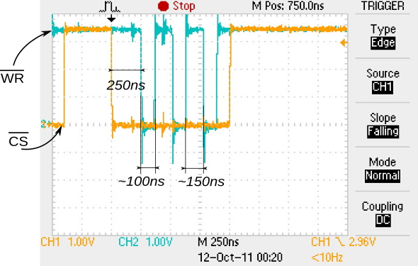
For example, in a microcontroller family like the HT32F125x from Holtek, Cortex-M3, the AHB bus clock and the APB bus clock are user configurable up to a maximum of 72MHz, which is also the default value. To this we have to add the processor instruction execution time. Thus, we can estimate the minimum possible latency time as four clock cycles (∼ 50ns), that is, once the instruction to move a pin has executed, it must go through the AHB bus to the APB bus to reach the peripheral, the I/O port itself.

As we’ve seen, it is possible for the processor to perform other duties but it can’t operate on that same port again, so the second order gets delayed until the first one can finish, what gives a period of eight cycles (∼ 100ns), as we can see on the figure, a capture taken during the development phase of a color display driver:

Another possibility is that the AHB bus internal structure allows pipelining succesive requests, this can help to reduce some cycles from the total time.

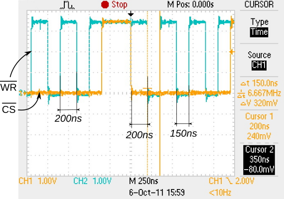
For example, for the TMPM330 from Toshiba, another Cortex-M3, the AHB bus clock and the APB bus clock are user configurable up to a maximum of 40MHz, and also the default value. This processor seems to have some form of pipelining in its AHB bus implementation, ’cause in the very same application we’ve observed a minimum period of six clock cycles (150ns), as can be seen in the following figure:

Up to here, everything is also valid for Cortex-M4 and Cortex-M0 processors.

The Cortex-M0+ processor can optionally have a Single-cycle I/O peripheral connected to its Bus Matrix, which, as its name suggests, allows performing input and output operations in just one cycle. That peripheral is memory mapped and can be accessed using regular data transfer instructions, but these are executed in one cycle instead of two cycles.

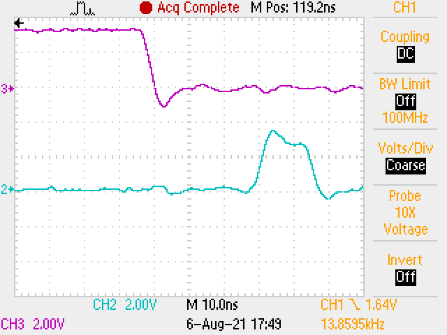
The next figure shows flipping a couple of GPIO pins on an STM32G071 running at 64MHz. The lower trace shows succesive set and reset operations in around 15ns:

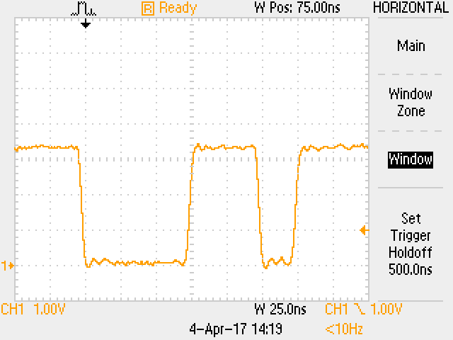
Regarding the I/O management process, and given that to operate on a pin we need to copy the required content from a register to memory, the actual operation in a single cycle would be limited to those cases in which it is possible to keep each required value in its own register and then use only memory transfer instructions in a row. The next capture shows the results of executing two successive read-modify-write operations, followed by two write operations, inside a loop (so we can easily see it), on a Holtek HT32F52231, a 40MHz Cortex-M0+. The first signal reset, at trigger time, includes the time needed to setup all necessary registers; so the time the signal stays in the high state is considerably longer. The first set can then be executed in three cycles (read, modify, write). The second reset takes two cycles (register load, write), while the next set can be executed in one cycle due to the optimizer being able to reuse one of the previously loaded registers:

This post contains excerpts from the book “Desarrollo con microcontroladores ARM Cortex-M3“, taken and translated with the author’s premission.

Manejo de GPIOs en ARM Cortex-M

Analicemos en detalle la operatoria para mover un pin de I/O.

La cantidad mínima de instrucciones mediante bit banding es de tres:

  • un registro del micro debe apuntar al registro de I/O
  • otro contendrá el valor a escribir
  • una instrucción de escritura indexada efectúa la operación propiamente dicha

Las operaciones siguientes que realicemos sobre el mismo port pueden hacerse con dos instrucciones, o incluso una si reutilizamos el registro que contiene el valor (0 ó 1).

Las operaciones de modificación de varios bits simultáneamente requieren de una lectura del port de I/O a un registro, modificación del registro, y escritura al port de I/O (excepto que el microcontrolador específicamente disponga de un hardware ad hoc como por ejemplo algunos STM32, pero hablemos del procesador Cortex-M en sí).

Cualquier operación que deseemos realizar sobre cualquier periférico, responderá en esencia a una de estas dos consideraciones vistas. Este proceso analizado demora muy poco tiempo en lo que respecta al procesador. Debido a la estructura interna de buses, el timing para acciones sucesivas sobre I/O viene dado por las transacciones en el bus AHB y luego el APB, sumado al tiempo del procesador para ordenar el cambio (ejecución de las instrucciones). Si bien cada micro tiene sus propios periféricos determinados por su fabricante, es común encontrarnos con tiempos de acceso de varios cientos de nanosegundos, debido a que el tiempo mínimo de conmutación en uno y otro sentido de un pin de I/O corresponde a la máxima velocidad de transferencia en estos buses, que es de dos ciclos de clock en cada uno.

Es posible que el procesador realice otras actividades en este tiempo, pero no que opere sobre el mismo port, en cuyo caso la ejecución de la segunda orden se demora hasta la finalización de la primera.

Por ejemplo, en un microcontrolador como el HT32F125x de Holtek, un Cortex-M3, el clock del bus AHB y el bus APB es configurable por el usuario, 72MHz como máximo y por defecto. A esto sumamos el tiempo de ejecución del procesador. Así, deducimos que el tiempo mínimo posible de latencia es de cuatro ciclos de clock (∼ 50ns), correspondiente al pasaje de la información de mover el pin desde la finalización de la instrucción hasta que pasa por el bus AHB y luego por el bus APB.

Como analizamos, es posible que el procesador realice otras actividades en este tiempo, pero no que opere sobre el mismo port, en cuyo caso la ejecución de la segunda orden se demora hasta la finalización de la primera, obteniendo un período de ocho ciclos de clock (∼ 100ns), como podemos apreciar en la figura, que corresponde al desarrollo de un driver para un display color:

Otra posibilidad es que la implementación interna del bus AHB permita realizar pipelining de sucesivas operaciones, con lo cual se reduce en algunos ciclos el tiempo total.

Por ejemplo para el TMPM330 de Toshiba, otro Cortex-M3, el clock del bus AHB y el bus APB es configurable por el usuario, 40MHz como máximo y por defecto. Al parecer este micro incorporaría pipelining en el bus AHB, pues en la misma aplicación hemos obtenido un período mínimo de seis ciclos de clock (150ns), como podemos apreciar en la figura:

Lo visto hasta aquí es válido también para Cortex-M4 y para Cortex-M0.

El procesador Cortex-M0+ incorpora de manera opcional en su Bus Matrix la conexión a un periférico que permite acceder a operaciones de entrada y salida en un solo ciclo: Single-cycle I/O. Dicho periférico está mapeado en memoria y puede ser accedido por las instrucciones corrientes de transferencia de datos, sólo que éstas se ejecutan en sólo un ciclo, en vez de dos.

La imagen siguiente muestra el movimiento de un par de GPIOs en un STM32G071 operando a 64MHz. En el trazo inferior observamos que un set y reset sucesivos se producen en unos 15ns:

En lo que al proceso de manejo de I/O se refiere, y dado que para operar sobre un pin es necesario copiar el contenido de un registro a memoria, la operación real en sólo un ciclo se limitaría a los casos en que es posible mantener los valores en sendos registros y utilizar sólo instrucciones de transferencia a memoria una tras otra. La imagen siguiente muestra el resultado de ejecutar dos operaciones de lectura-modificación-escritura sucesivas, seguidas por dos de escritura, dentro de un loop (para poder observarlo fácilmente), en un Holtek HT32F52231, Cortex-M0+ de 40MHz. El primer reset de la señal, al momento del disparo, incluye el seteo de los registros necesarios; por eso el tiempo en estado alto es considerablemente más largo. El primer set ya puede ejecutarse en tres ciclos (lectura, modificación, escritura). El segundo reset se ejecuta a los dos ciclos (carga de registro y escritura), mientras que el set siguiente se ejecuta en un ciclo dado que el optimizador del compilador ha podido reutilizar un registro cargado con anterioridad:

Este post contiene algunos extractos del libro “Desarrollo con microcontroladores ARM Cortex-M3“, con permiso del autor.

The strange case of the board that refused to power down

This happened a while ago, in a galaxy not so far away, and where many men have gone before.

Me and this colleague had designed this simple power-on circuit for a portable battery-powered instrument; where a MOSFET bypassed the power-on push button after the microcontroller started, as can be seen in the following diagram.

To power on, the user presses the button, the microcontroller gets powered up, does its initialization sequence, and sets POW_CTRL high, enabling the MOSFET, what keeps the microcontroller powered on after the user releases the button. To power off, the user would press the button again (some time after the initial power up), what is read by the program at the SW_OFF pin, disabling the MOSFET and entering a harmless loop. Once the user releases the button, voltage at ON_PWR begins to decay, and the microcontroller will eventually power off as the capacitors discharge.

This worked great in the lab and in the first units we produced for our customer. But some time later, on another production lot, one or two of the new units could not be powered off; they would restart instead.

I was the one perpetrating the hardware, so I was unanimously elected to be the one in charge of solving this mistery and find the logical reason behind this esoteric behavior.

Having all “failed” units and a couple of “working” units in my workbench, I instructed Mr. O to take a look at the circuit.

The “working” units exhibited a nice exponential roll off where the supply voltage was graciously and monotonically falling down, though some parts of the curve showed changes in the slope.

The “failed” units showed a more pronounced change in slope, with a strange tendency to go horizontal just before the microcontroller would decide to restart. The cyan trace is the supply voltage at ON_PWR, just before an LDO, while the orange trace is the voltage at POW_CTRL, with a nasty weak pull-up resistor to the battery voltage (through that resistor going nowhere in the schematic, part of a more complex circuitry but normally left open or grounded otherwise) to show when the microcontroller had set its pins in Hi-Z mode (at reset time…). (I promise I only did this q&d hack to take the pictures)

Finally, one of those later units was kind enough to let Mr. O show me a small rise in the supply voltage; yes, that small cyan dot within the red circle, just before the orange trace rising edge. I know it can be just measurement noise, but, it looked like the voltage was rising just before the reset was to occur. Yes, no one had pressed the button, and if you are blaming the LDO, well, for all purposes I’ve tested those chips to behave like a wire for all voltages below the regulated one.

My (perhaps educated) guess is that, once the MOSFET was turned off and the microcontroller supply voltage was going down as the main capacitor was discharging, the microcontroller internal circuits (peripherals) took turns powering off and so draining less and less current. That current was provided mostly by the main electrolytic capacitor, and what I was observing was its dQ/dC when dQ was being decimated by di being drained as dt went by; and to that, substract di times its ESR (Equivalent Series Resistance, which for this purpose would serve as an umbrella for perhaps some group of subtle chemical issues). That would explain those changes in slope…

Apparently, in some units, those differences in current when the peripherals turned off and the nonlinearities in the capacitor ESR would cooperate to alter the monotonic behavior in the supply bus (and even perhaps be seen as a small rise in voltage), situation that would trigger the BOR (Brown-Out Reset) and the power-on reset circuitry, and so the microcontroller would restart, enabling the MOSFET again.

Fortunately, due to the power-off functionality, we could check on startup whether the button was being pressed or not. A button pressed condition was the typical power-on situation, while the button not being pressed would signal one of these nasty BOR compulsive restarts, situation we would gladly recognize and elegantly ignore, detouring to a harmless loop waiting for either the power to come definitely down or the user really press the button (’cause sometimes, only sometimes, buttons do bounce; but I guess you do know about that… don’t you ?).